|
For a while, I have been faced with some random issues related to some of my printers always starting way too high on the Z axis and today I have finally realized the solution for this issue. First, be sure that your bed is leveled, or if you use auto bed leveling that your probe is calibrated properly and it's Z offset will make your nozzle be a sheet of paper away from the bed. If you are still having issues with it, here it's how I solved it:
I recently started building a Hypercube 3D printer by tech2c, which I call the Megacube because it has a 300x200 bed. So, after testing that everything worked and calibrating my inductive sensor (You know calibrating it's offset and so on) and I made a print, which in this case was a Bulbasaur from pokemon and it stuck properly to the bed. I go to sleep, come back in the morning and for the life of me I could not get any of my prints to stick to the bed. The nozzle always started printing at about 2mm away from the bed, which was way too far for anything to stick. I knew it was not my slicer settings (In this case Cura) because I did not change anything that would deal with Z heights or layers. I kept poking around and I found that nothing I changed in the slicer changed anything at all, so I went to the firmware and started poking there. I am using Marlin so I went straight for the "config.h" file. In there I realized that there was actually something that I changed before going to sleep that was causing issues. It was the line: #define MIN_SOFTWARE_ENDSTOPS Which I had unncommented before while I was doing some tests with my inductive probe, when I commented it out: //#define MIN_SOFTWARE_ENDSTOPS It ended up solving the issue and giving me the proper distance from the bed every time I started a print. After that, every other print stuck to the bed for me.
0 Comments
Hello everyone, sorry that I have not written anything in the past months. I have been mostly focusing on my Youtube channel and school, which took most of my time, and did not allow me to write more often. Today I want to write about something other than 3D printers. I have been doing some researching for a while ever since I got my Orange PI PC, I have tried a lot of the community created images and they seem to have the tendency of all having the same issues. They all most of the time do not allow you to use all of the USB ports on the board at the same time, tend to have old kernels, as well as having overheating issues (which seems to be the worse of them all). I have only found one image that seems to work decently so far and it has been the Ubuntu mate one. If I am not mistaken, this image is a Ubuntu 15.10 based image. It works well, no USB issues or any of that, but it still has the overheating issue. The overheating problem can be fixed by following some tutorials, I followed this video and it helped me solve the overheating problem in it. He goes through an unboxing, setup and fixing of the image. Still, I wanted to find a better option that will not require any setup, other than burning the image and having everything ready to go, and I did find it. While I was doing digging online, I found a site that kept constantly popping out, which I never really paid attention to. This site was the Armbian site. I checked it out and they had an image of Debian Jessie which perfectly works out of the box. 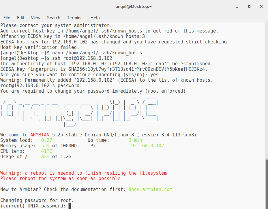 When you turn on your Orange Pi PC while connected to the Ethernet, you will be able to ssh into the device by logging it as root with the password "1234". Right away, they will ask you to change your root password and register a new regular user to use your device with. They also give you the recommendation to reboot your device in order to resize your partition size in order to use all the available SD card space, which is very nice. The first login always seems to take a little while, so be patient. 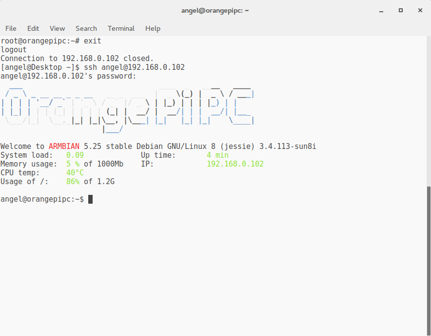 The CPU seems to be slightly overclocked by default but it should not be a problem. It is overclocked by 0.09Ghz which is not as bad as the 0.3Ghz in the community images. When executing the command "cat /sys/class/thermal/thermal_zone0/temp" to check the temperature of the CPU, I got a range of 39C - 41C while in idle. This is very good in comparison to the community images, which will hover around 49C and 60C for me, even after applying the thermal fix. 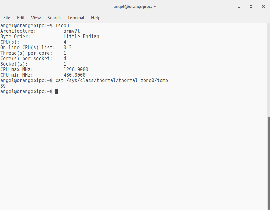 Overall I have to say, I am very pleased and impressed as to how well these images have worked for me so far. The usage of these images at least for me, gave a bigger sense of reliability and worth to this Orange Pi PC boards. I will be sure to try some of the newer boards that include WiFi chips as well with Armbian and report on how they perform. If you would like to give these images a try, you can download them from the link below. https://www.armbian.com/orange-pi-pc/ Don't forget to check out their quick start guide, they offer very good tips on how to properly set up the system. Hello readers, I just wanted to let all of you know that the files for the Heimdall 3D Printer are on Github. You can go through them, make changes, or even contribute to the project. You can also now build yourself one, and modify the printer the way you like and then contribute the changes that you have done to the main project.
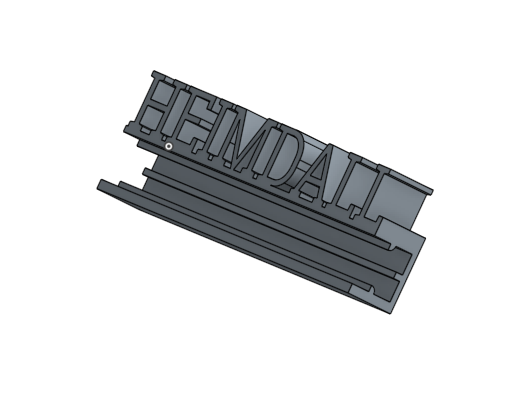
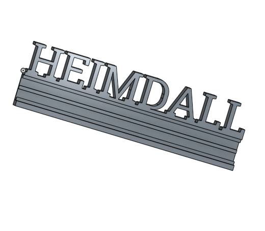
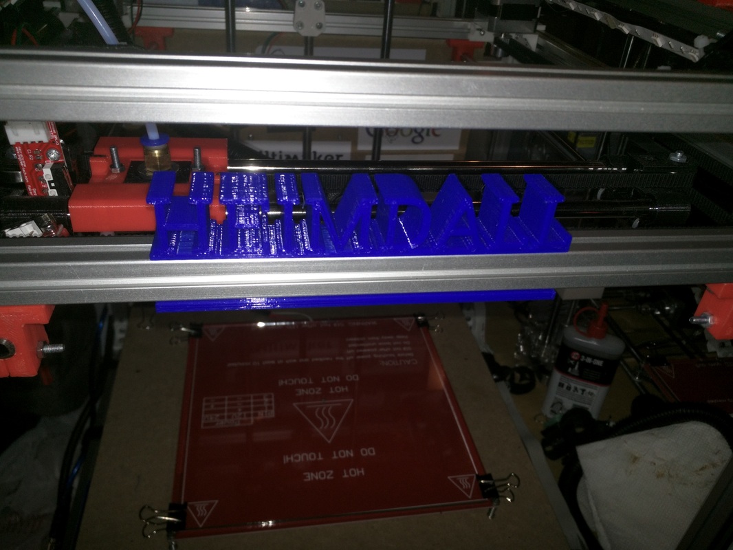
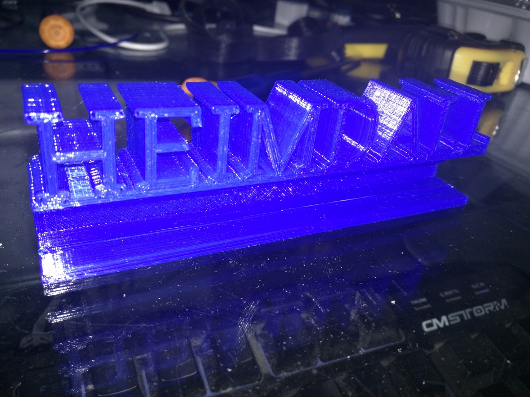
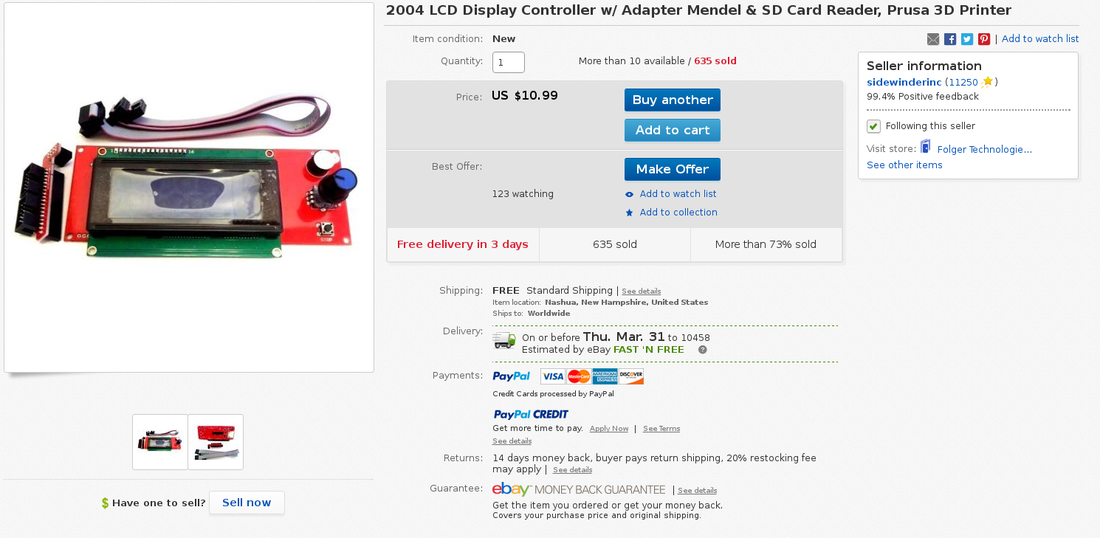
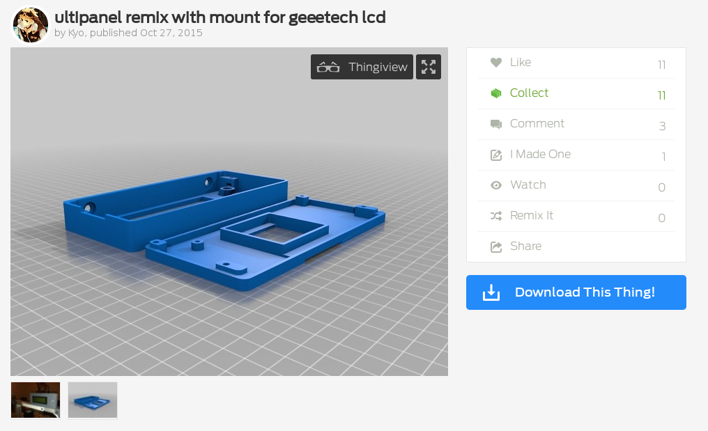
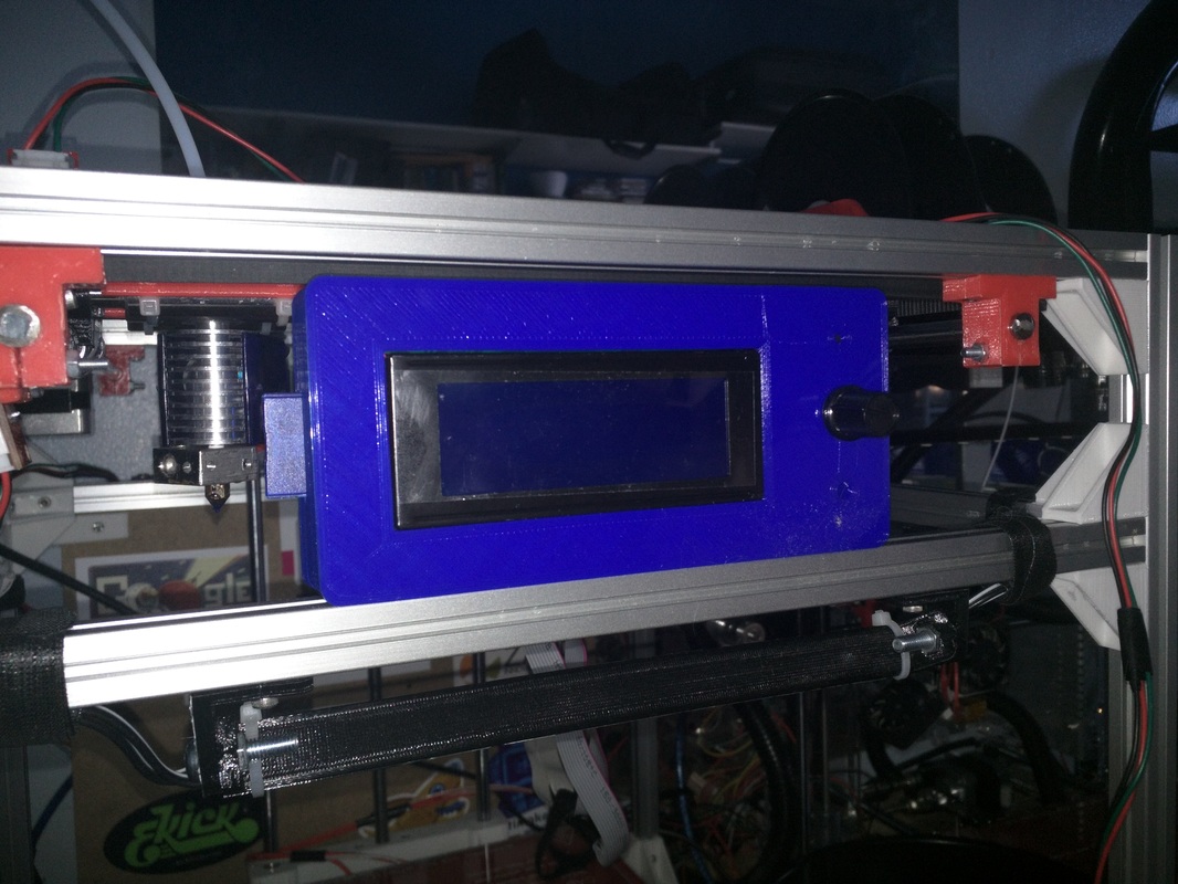
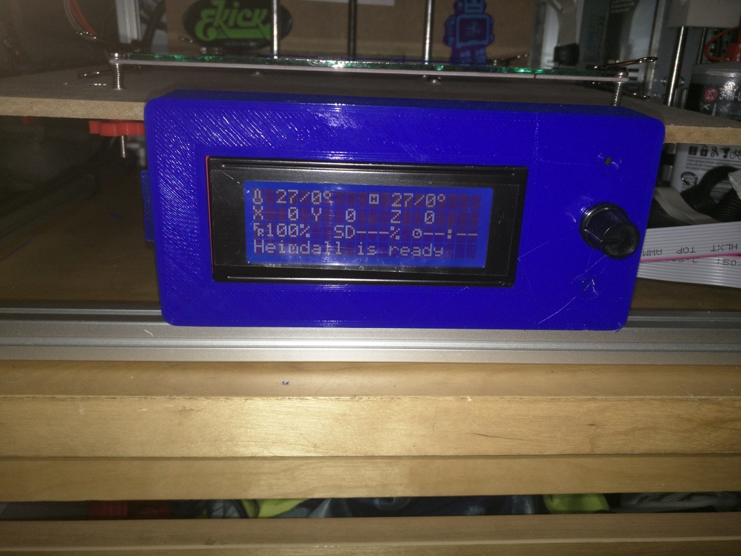
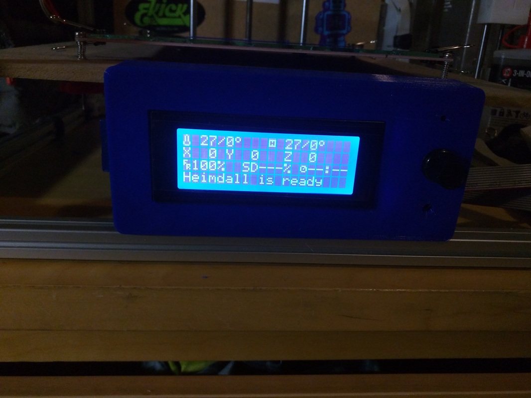
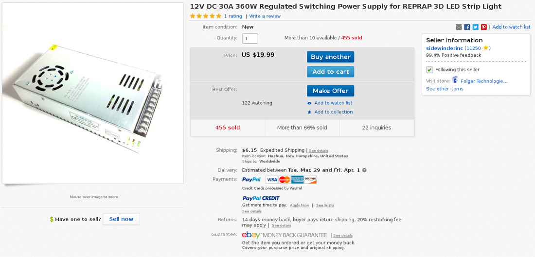
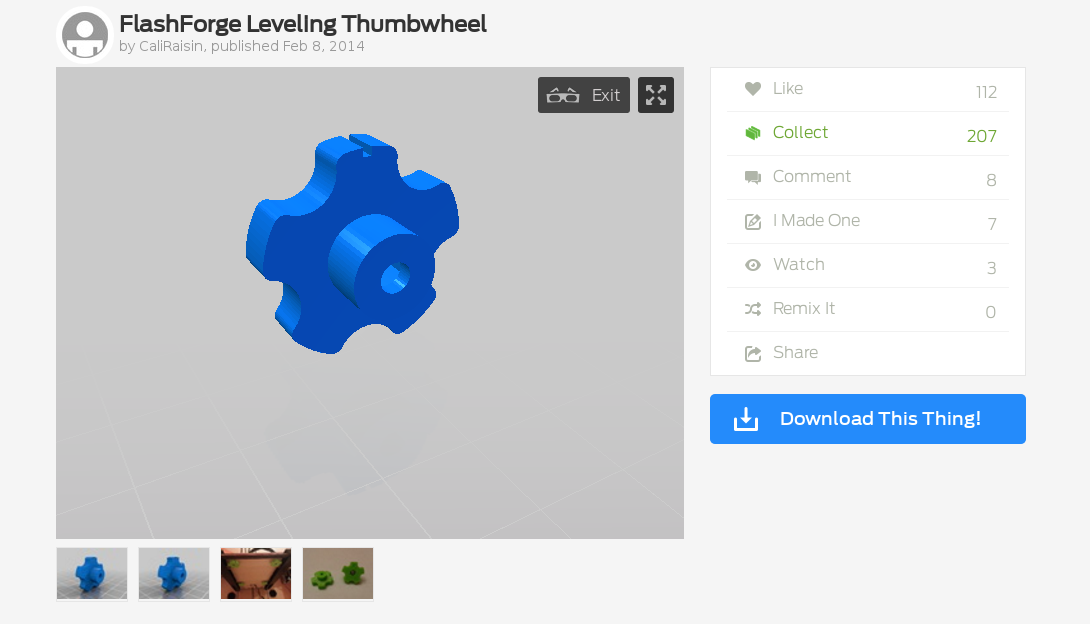
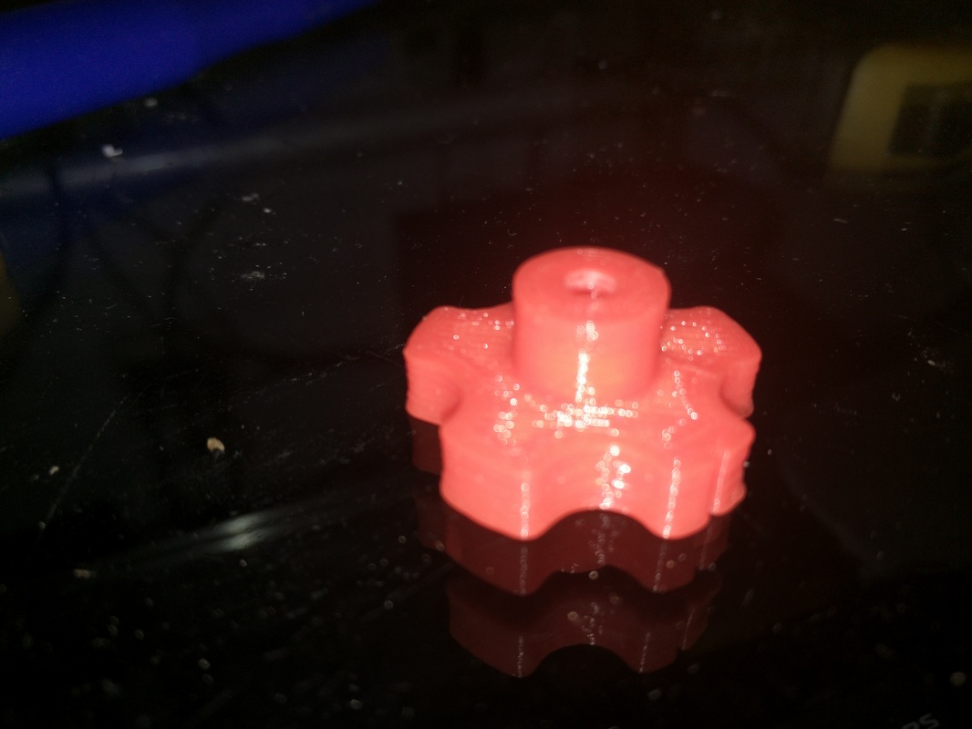
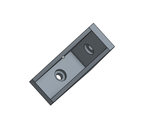
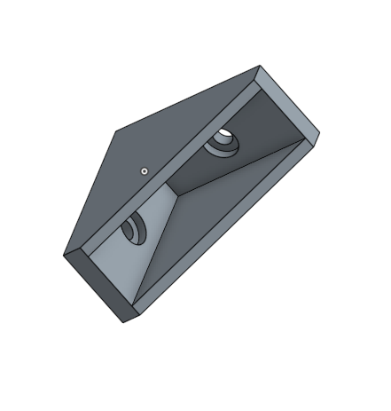
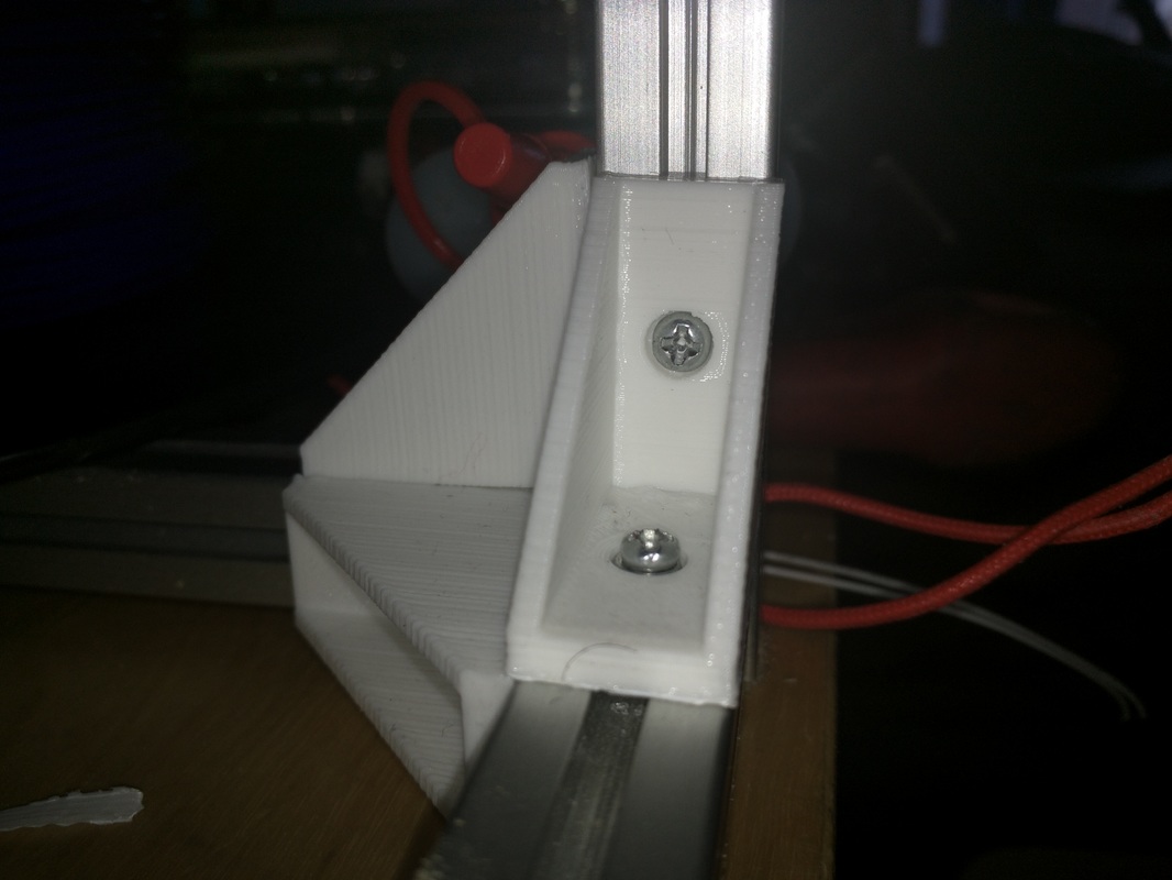
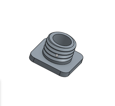
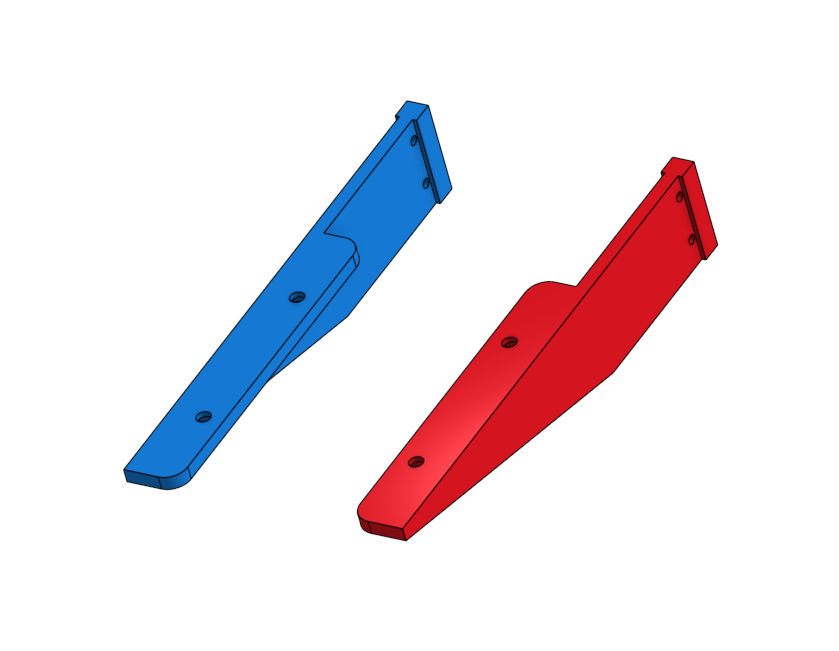
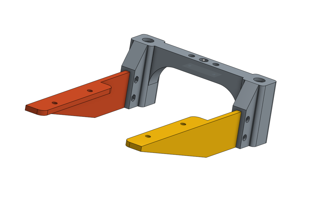
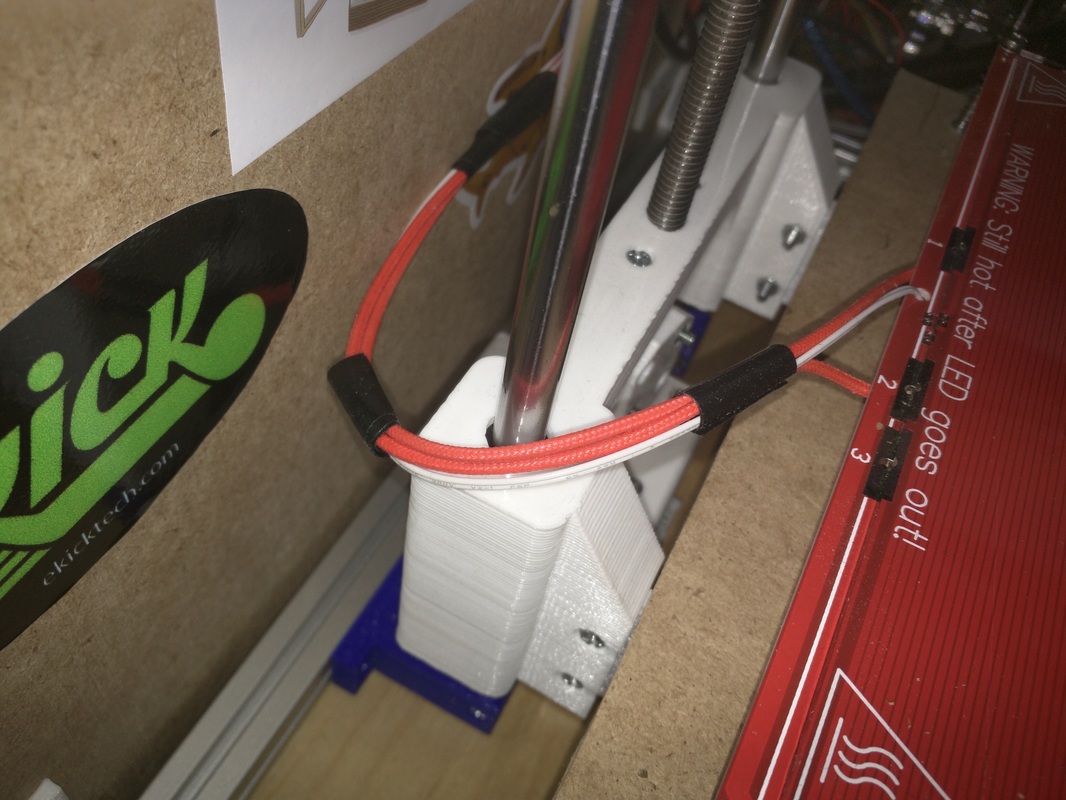
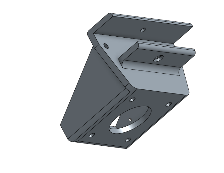
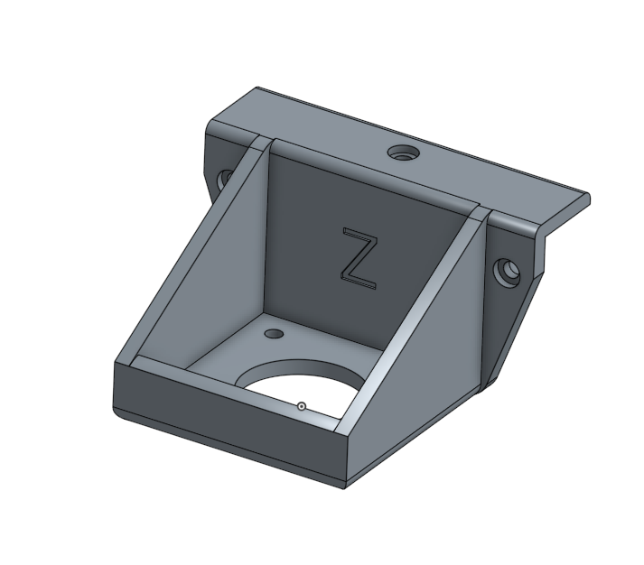
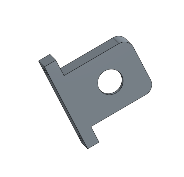
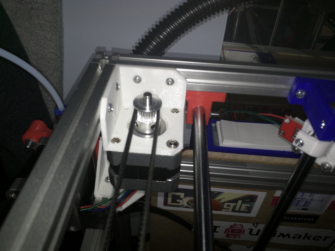
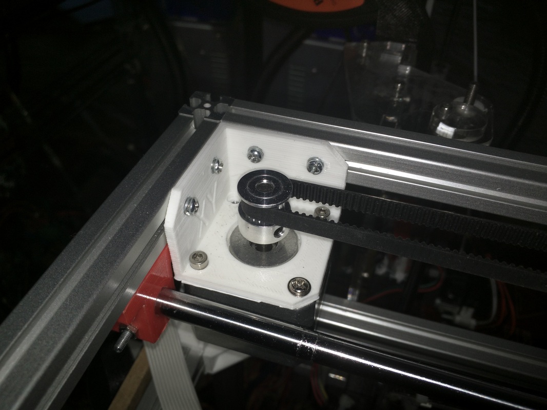
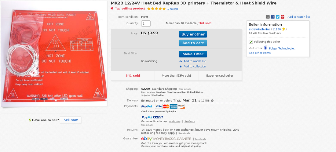
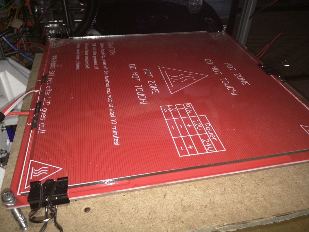
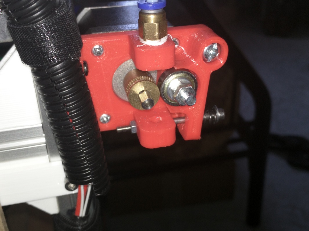
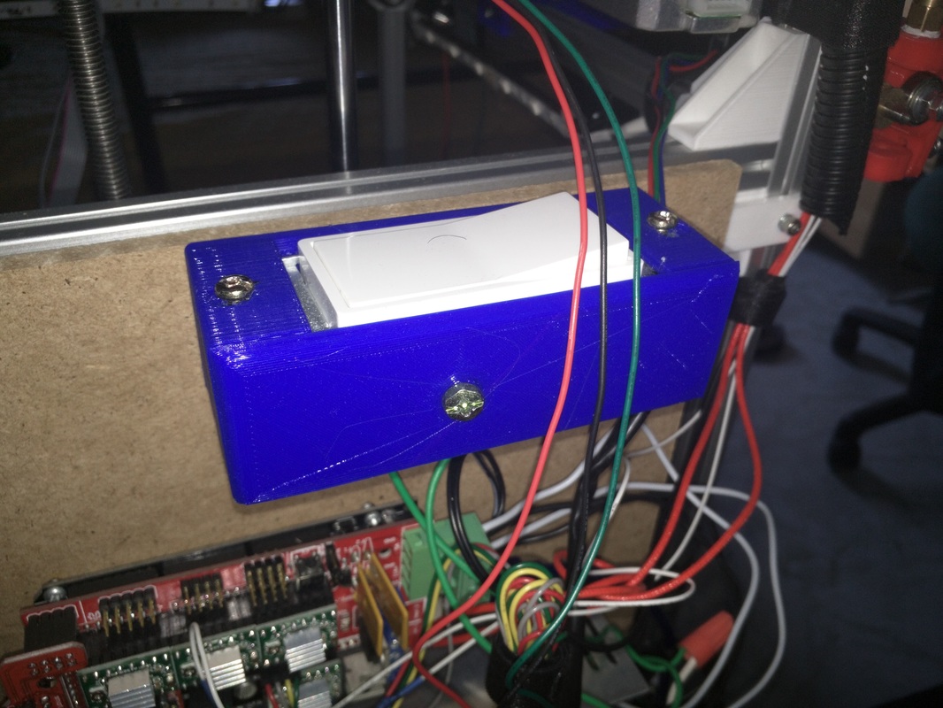
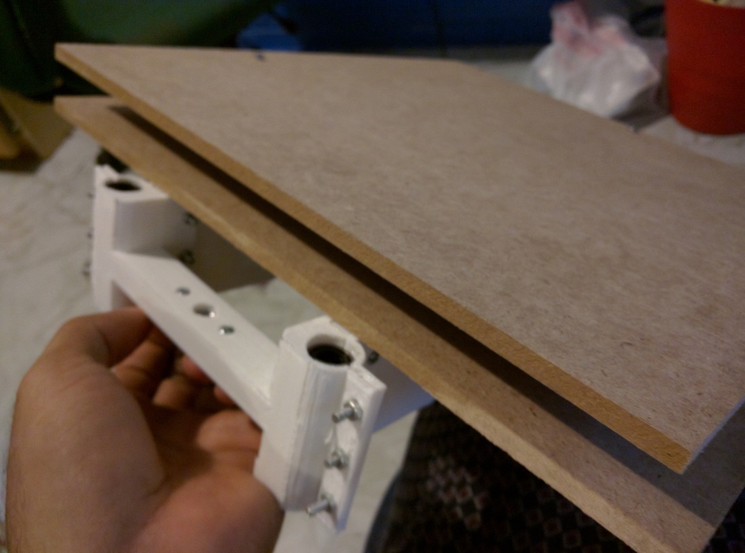
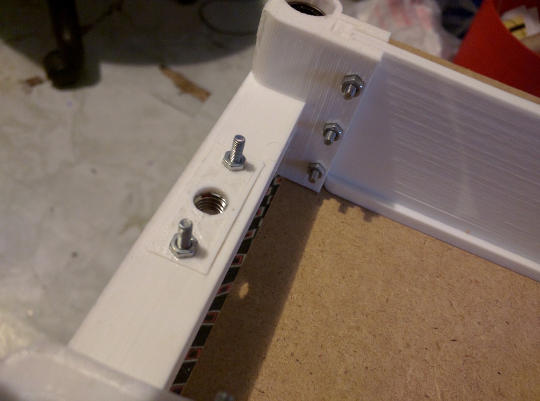
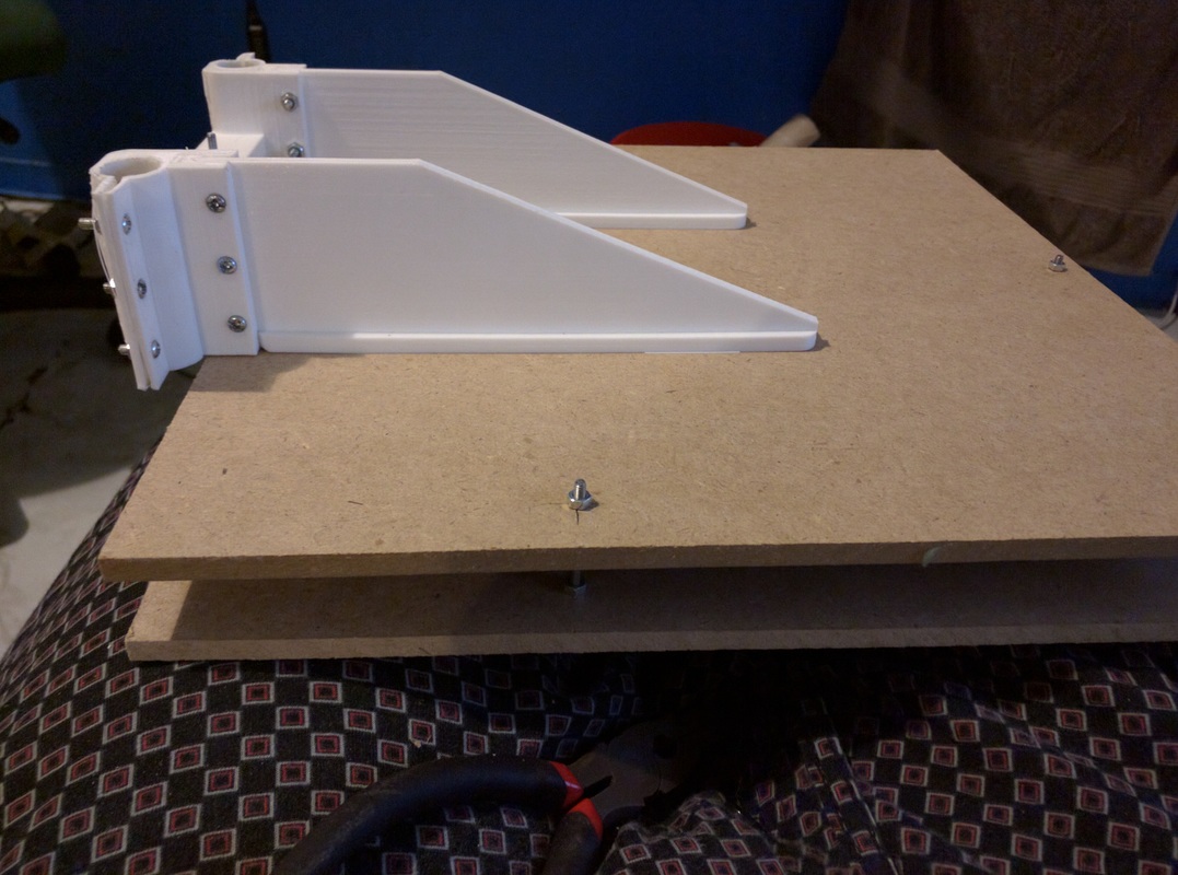
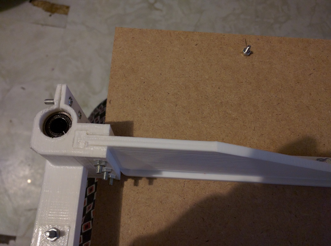
Here is the link to the Github repository: https://github.com/frostclaw20/Heimdall3DPrinter In there you can find the Bill of Materials, which contains all the parts needed to build the 3D printer. You can also find all the 3D printable parts, which also contain their CAD files for easy modification of the parts. These files also include some optional parts, which means that the printer will be able to function without them, but if you would like to get the functionality that they provide, you can still print them and add them to your Heimdall 3D printer. The Marlin Firmware for the printer is also included within the files, which means that you can easily flash it and get up and running with your printer. The Marlin Firmware is configure to work with my current setup, but if you want to make your printer bigger or modify it in any way, you can change the code to reflect those physical changes. Included are also the printing profiles for Cura and Slic3r, which gives you more options in terms of slicers to use with the Heimdall. All the changes that I will be making in the future to the printer will be added to the main repository of the Heimdall. Hello everyone. So, a lot has changed ever since the last update. There has been a lot of parts of the printer that have been redesigned and many parts which have been changed. So far, I believe that the printer right now can provide reliable high quality printing. There are some other parts which need changing other than the ones listed here, like for instance the linear bearings because they are old and really loud. Overall I'm really liking the direction in which the printer is going. I have also done some streams on Twitch.tv in which I designed and printed parts of the printer, so if you were able to tune in for those you are great! Heimdall Front LogoSo I made this logo that if you would like, you could slide into any of the 1515 extrusions to display the name of the 3D Printer. Just a really simple design, nothing too fancy about it. In the newest build of it, I replaced the logo with the LCD because the LCD takes less space there and ends up looking far better there. New LCD Display (Reprap Discount)I ended up adding a RepRap discount LCD display to make to make the printer overall more reliable and portable. This will allow me to take the printer wherever I need and just have the SD card with the gcode of the prints that I need there. I can also move the axis and do really whatever I want with the printer without relying on a USB connection to a computer. So far it works pretty well and the Marlin firmware has been adding new features to these LCDs that I need to test out as well. I purchased this LCD from the Folgertech page on Ebay. The cover for the LCD is from the thingiverse user Kyo: http://www.thingiverse.com/thing:1094510 Also I need to thank the people who helped me get the LCD and the power supply though donations on Facebook. I love you guys! New Power Supply (12v, 360W)I got this power supply in order to power the new heated bed. The printer used to have an old 150W power supply but it was not enough to power the heated bed, due to the amount of amperage required to power it to normal printing temperatures. This power supply should have enough power to power the hotend, heated bed, electronics and LEDs. I purchased this power supply from the Folgertech Ebay page. Again, thank the people who helped me get the LCD and the power supply though donations on Facebook. I love you guys! Bed leveling thumbwheelThese thumbwells are just to facilitate the leveling of the heated bed. They works fairly well and they just need a M3 nut inside of them. This model comes from the user Caliraisin: http://www.thingiverse.com/thing:243998 Redesigned Corner BracesI decided to make some changes to the old corner braces, and added sides to them so they will not be able to bed in any circumstances. I also made them slightly longer for them to have more space and mass, which helps with rigidity. Overall the frame seems to be more rigid with these in comparison to the older ones. Redesigned Z Axis CarriageWell, these parts are one of the parts that took the most time to get them to work properly and a lot of prototyping went into them, but at the same time they are very smart designs. So these parts are pretty much the Z axis part to which a wooden board can be screwed to and then the heated bed goes on top of the wooden board. I used MDF for the wooden part because it is completely straight, does not weight too much and it is cheap. The MDF was screwed to the two leg parts (red and blue parts) and those are then inserted in slots in the main body and screwed. They end up being really tightly attached to the main body. Now this is the interesting part, the linear bearings for the 8mm rods are inserted in a hole at the bottom of the main body, and then the hole is closed with a 3D printed threaded cap. The cap pretty much presses the bearing in place and does not allow them to wobble or move on the inside, and at the same time ends up being tightened really well to the point that the cap wont move from its spot unless you use tools. This design is great because it uses less screws than my older design, it is more low profile, far sturdier and reliable, while keeping all the parts 3D printed. New Z Axis Motor BracketI decided to redesign the Z axis motor mounts because the older ones seemed to be really flimsy and anemic. These attach fairly well to the 1515 and do not move at all. I designed these to go at the bottom of the printer base. It lays almost flat with the base of the printer but not quiet, so the printer's bottom 1515 extrusions need to be moved up slightly to accommodate for it. This part was actually designed live in one of my streams. New Z Threaded rod StabilizerThis is a stabilizer for the Z axis threaded rod. I found that sometimes the rod will wobble a little bit when moving up or down which could cause issues when the carriage reached close to the ends of the axis. How these work is that there is a skate bearing which is press fitted in the middle of the hole, then the rod comes through the hole of the middle, which rests in the middle of the skate bearing. When the Z axis rod spins, it spins the with the bearing and does not wobble at all. I decided to use skate bearings because the shaft fits almost perfectly inside of them and they are also extremely cheap. New XY Motor MountsThese are some new brackets for the XY axis. I decided to design these because the old ones that the printer had will have the motors laying upside down and I didn't like that really because if one has them at the top of the printer, they will stick out too much out of the printer, and if something happens to the top of the printer it could end up damaging the motor. I rather have them within the frame of the printer as they are now. New Heated BedThis is a conventional Prusa bed that I decided to purchase for the printer. I decided to buy this heated bed because with it I can print many more materials, not just PLA. Don't get me wrong, the wood bed with painters tape worked very well and prints stuck to it fairly well, but it was not as reliable as having a proper heated bed. Now I can print ABS and other materials with this bed as well which is great. I find that this heated bed tends to heat up way faster than the heated bed in my Folgertech Prusa i3, they are the same heated bed and have the same power supply and electronics and it seems to just get to printing temperature much faster. I will have to do a test to see how fast it gets to temperature in comparison. Configuring the firmware to use a heated bed was really not challenging and worked well at the first try. Redesigned 8mm rod Holder for Z axisI had to modify these slightly because of the new Z axis motor bracket. It seems to be 3mm thicker than the older one, so I had to account for it with these new Z axis shaft holders. They are just 3mm longer pretty much. New Bowden Extruder MotorThis was something that I had issues with for a while. No matter if I was using a direct or bowden extruder, they motor will get extremely hot, to the point that it might damage it. When the motor will heat up, it will just stop working properly and will start under-extruding or extruding at all. I realized that I had this motor around, which was from my old OneUp 3D Printer and decided to put it the printer instead of the older motor, changed the Vref of the stepper driver for about 0.700V and it worked beautifully. This motor seems to have way more torque compared to the older one and can do the same job and not even get warm at all. It is a little loud though, and when retracting it makes a loud noise which I will have to play with my retraction settings to reduce, but other than that it works fairly well. New Boweden Extruder MountThis is a bowden extruder mount that I designed. It works like any other bowden extruder design out there, it uses one of those M10 fittings that some bowden extruder hotends use at the top and uses a small bearing and MK7 gear. I might have to get back to this extruder because it does not work extremely well and might need modifications. This is one of the bowden extruders which clamp the filament between the bearing and the gear to push it through the PTFE tube. Enhances in X CarriageNot a lot has changed with the X carriage really. I decided to use the teeth that can grab the GT2 belt instead of using zipties to hold the belts to it. This is far more reliable and does gives more X axis travel. New KillswitchI added a big beefy switch to the back of the printer in order to work as a killswitch. I added one of these as well to my Prusa i3 because they are simply amazing. If something is wrong with the printer to the point of no return, anyone can come and just slap the switch and turn it off. For instance, one time I was printing something for my brother and the print detached from the bed and my brother just slapped the switch and turned it off, which ended up saving a lot of plastic and hassle. I believe that everyone should have a killswitch in their printers no matter what, they are life savers. Mines is connected between the mains cable and the power supply. Hello guys. So not long ago I got my Dz09 smartwatch, and I realized that the app that the watch tells you to download does not even connect properly with the watch at all. It for some reason seems to just not connect at all and the functions that need the app to properly work do not work. After doing some research I found some Youtube videos in which the people that were reviewing the watch were using an application called FunDo SmartDevice. It seems to also work with some other smartwatches from china too, so if you have a smartwatch similar to the DZ09 you should try it out.
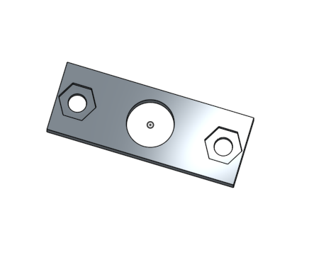
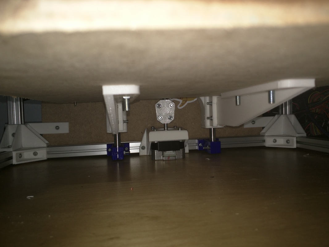
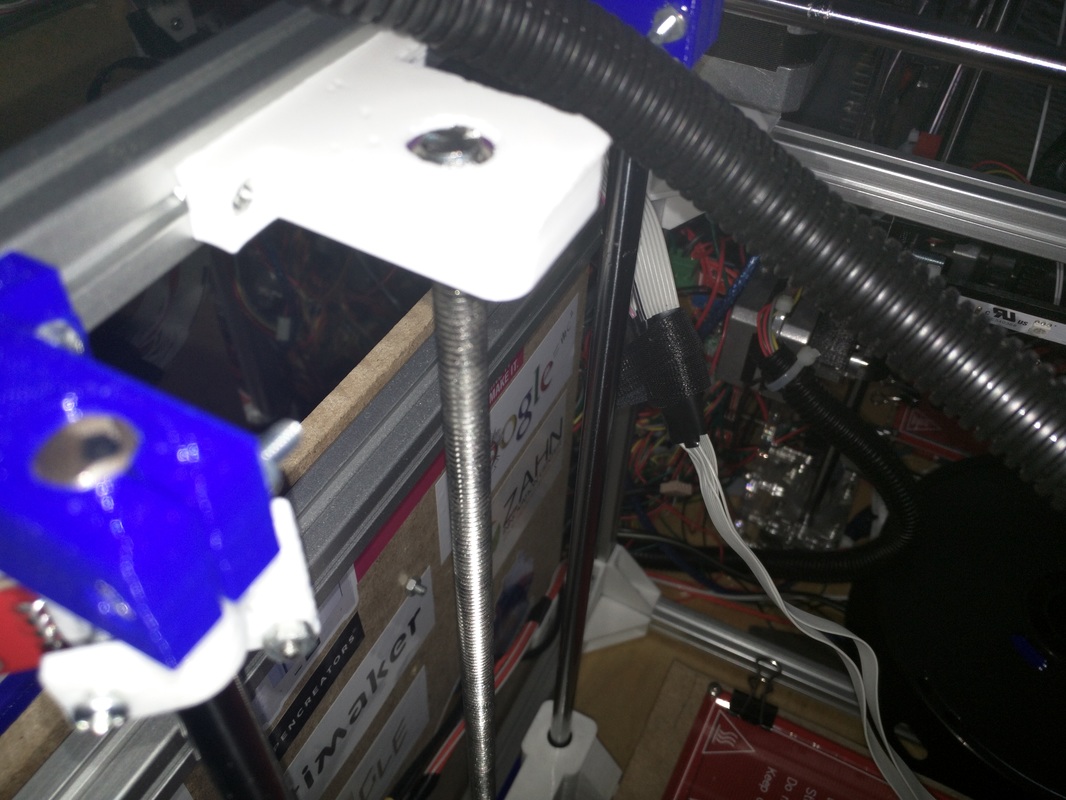
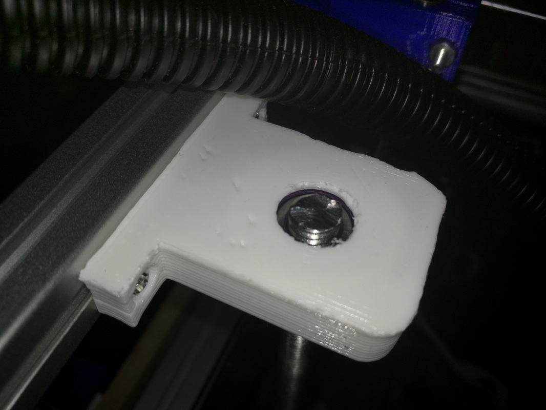
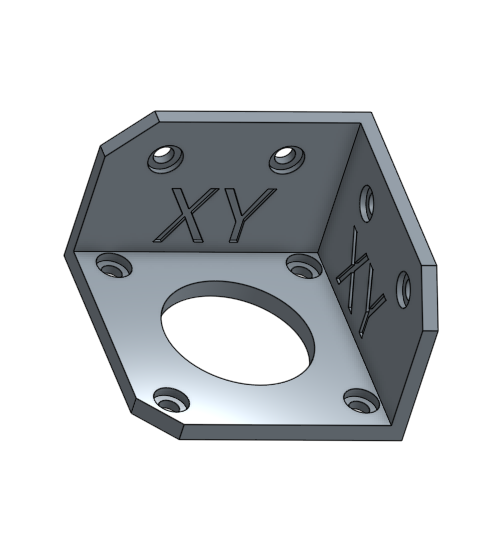
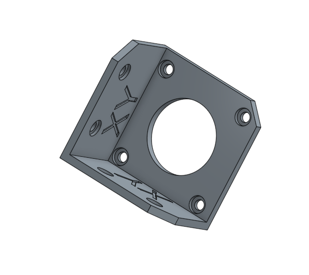
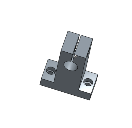
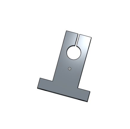
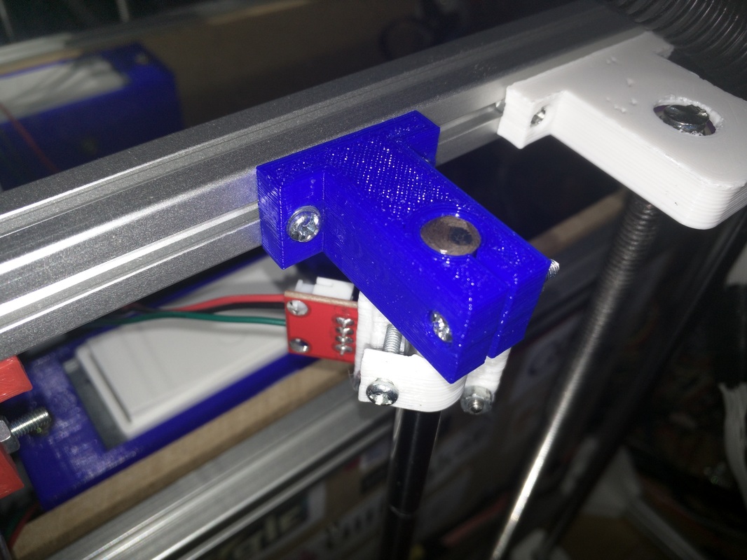
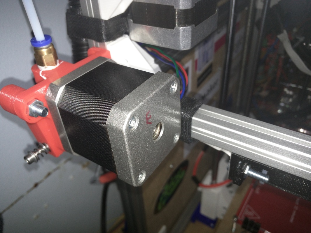
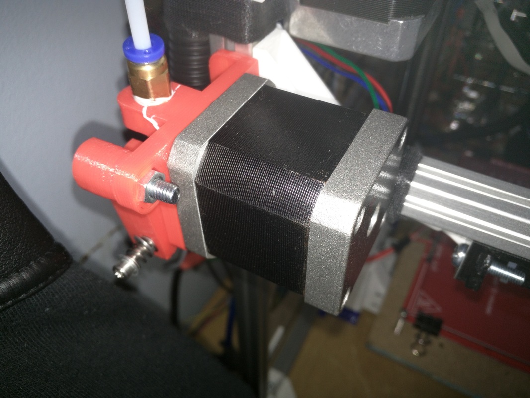
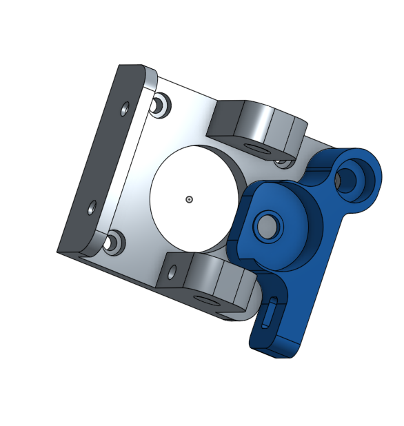
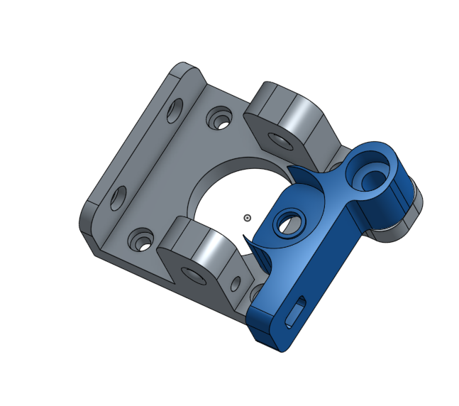
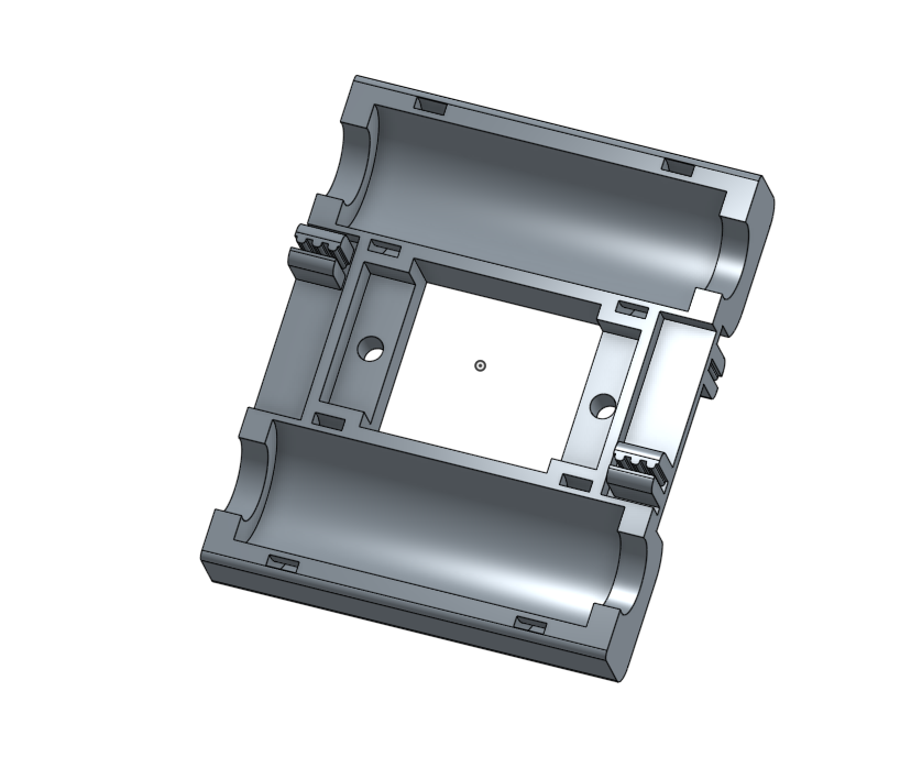
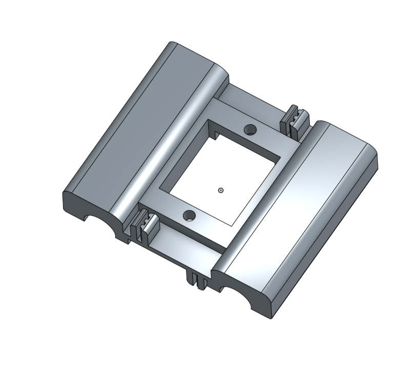
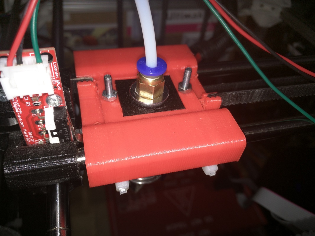
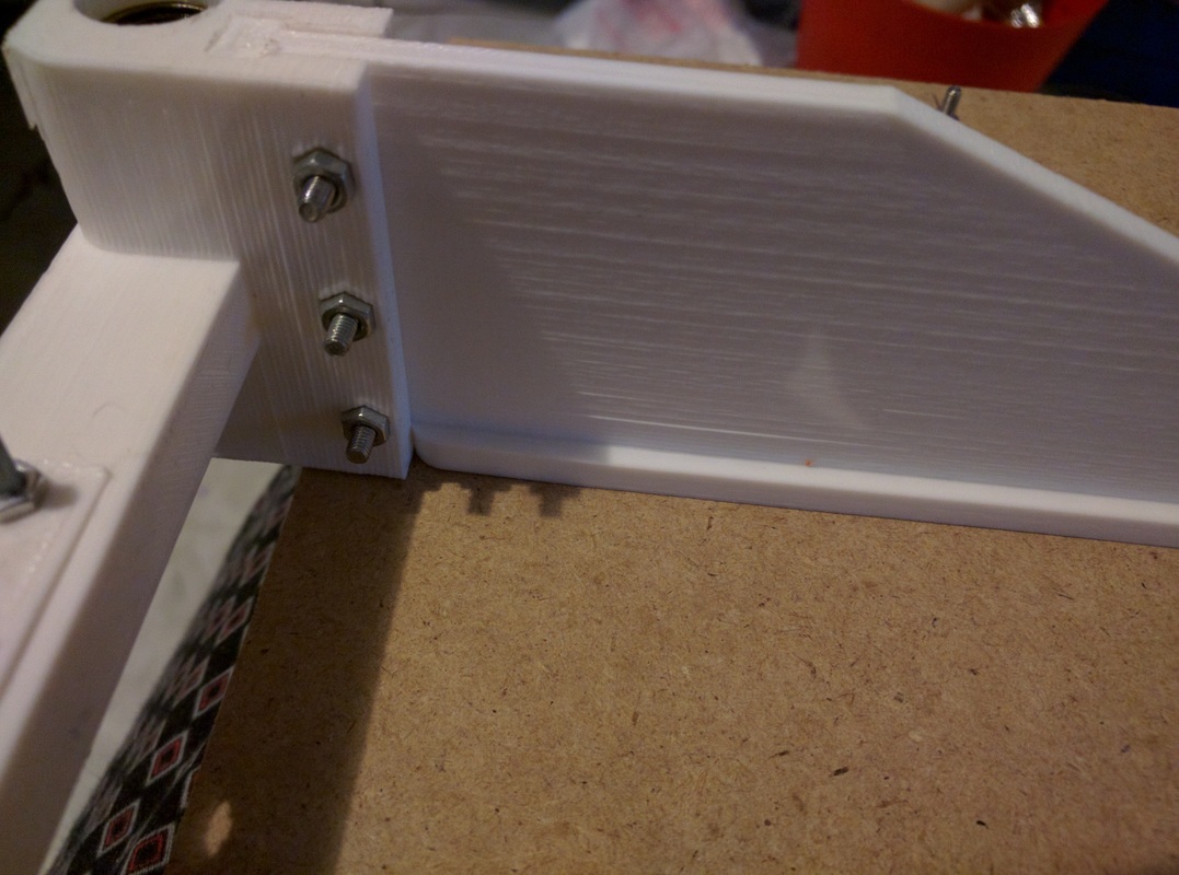
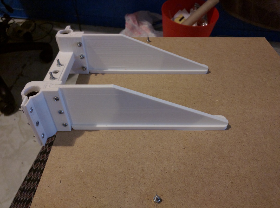
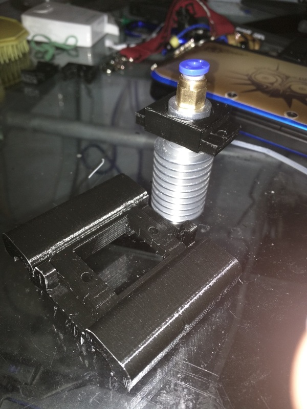
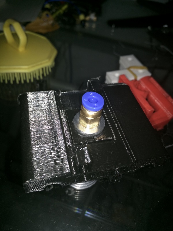
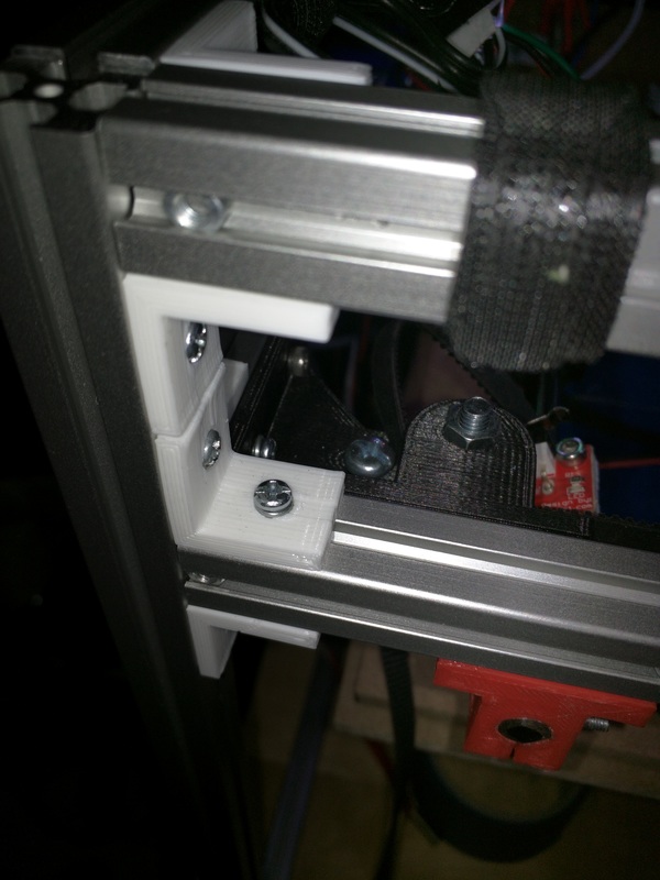
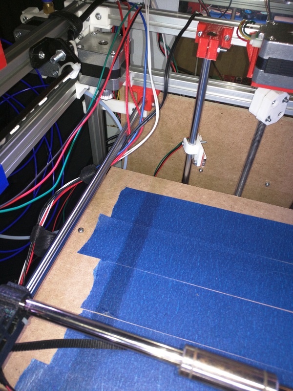
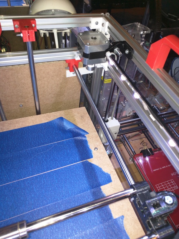
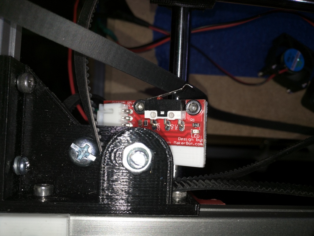
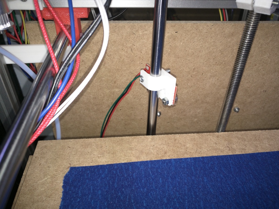
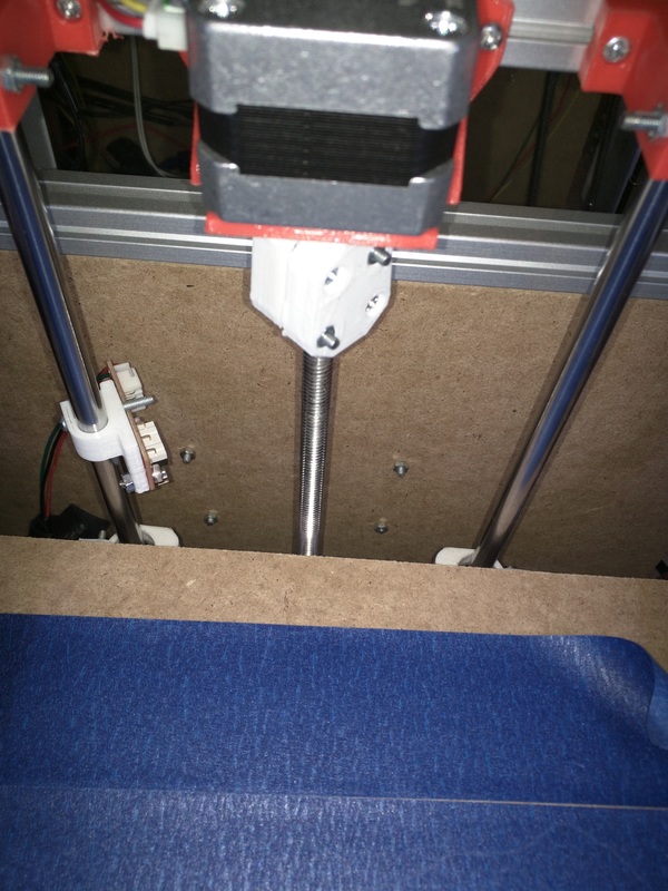
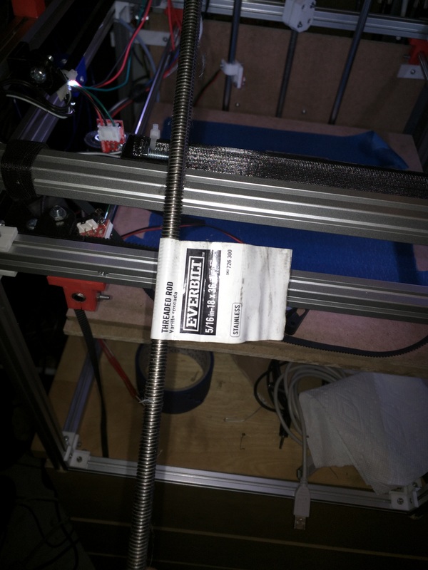
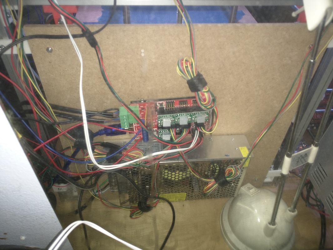
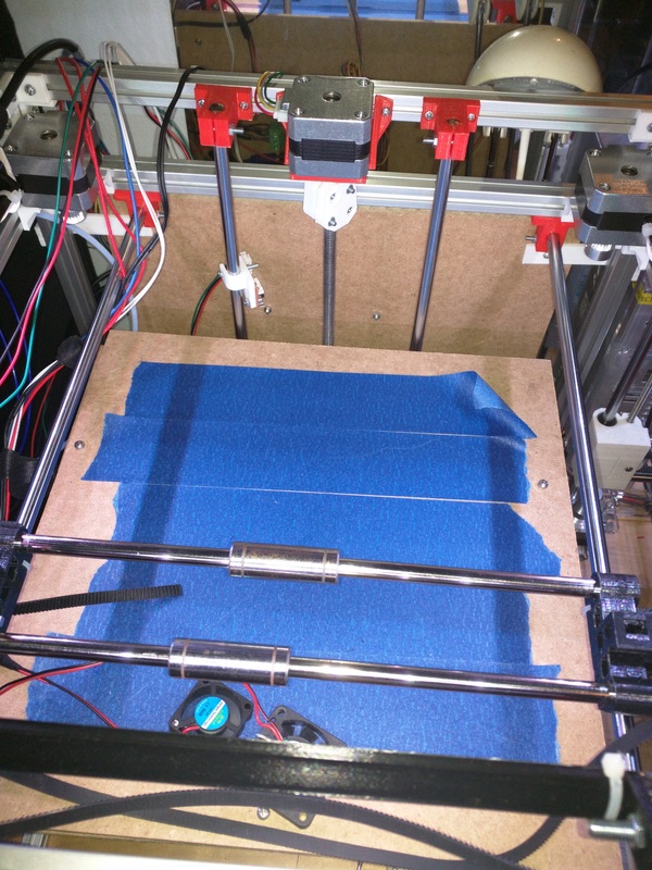
You can download the FunDo SmartDevices app from here. So far the DZ09 smartwatch has been far from impressive. Battery life at least for me has been really crappy. I has been a really annoying issue for me because the watch is advertised for 150 hours on standby, but I can't even get it to run for 2 days casually checking the time and notifications on silence mode. Extremely disappointing. I had the watch on vibration mode and it would not last more than 6 hours on. By the time I came home from college it would be already dead. I understand that these watches consume a lot of energy because of the display and other connectivity but I had am i5 smart bracelet from Gearbest too which used to last about 2 weeks per charge, have vibration and a small display. Not only that but the fact that I do not have vibration to let me know that I have received a notification makes it pretty much worthless because it is mostly what I want the watch for. What also bother me is that these companies selling them usually miss-advertise products like these. I have owned 3 of these type of smartwatches and they just disappoint me. If I find a way of increasing the battery life a little more I will let you guys know. Other than the battery, everything seems to be working well. Connectivity with the phone is good. Camera has pretty crappy quality but I guess you can't expect much from it. You can use a sim card and an micro sd card but I have not tried any of them yet, mostly because I don't need them because they seem like useless features for a smart watch that is supposed to be a complementary piece of hardware for your phone. The watch also have a lot of customization compared to other watches out there. You can set custom ringtones that you can keep in the micro SD card and change through some themes that they have, as well as animations and watch faces. Anyways, that's about it for me today. Let me know how if you have a DZ09 watch and how it is performing so far for you. If you have any questions you can ask them below. Hello everyone, today I bring you an update on what is the Heimdall 3D printer. This one is the third update of this series. A lot of changes have happened since the last time I wrote an update. A lot of these changes and fixes helped the printer actually become active and work properly. I will be explaining the changes made and why they were made, as well as how they improve printing. I have already uploaded some tests that I have done on YouTube, if you would like to see them, here they are: Why Version 2?I decided to make it version 2 because of the large amount of changes and improvements that have gone into this printer. There have been a lot of remade parts, improvements and tons of hours of printing and prototyping. Changes in Version 2Printing BedTons of changes went into the Z axis carriage. This is now divided into four parts that go in together. Two of these are the legs, which screw to the main body using three M3 screws. Then they use three M5 screws to attach to the wooden platform that holds the printing bed. The main body contains the two LM8LUU linear bearings, which are tightened by three more M3 screws. I wanted to use screws because I do not want to be breaking zipties to get to them. In the middle of the main body there is the nut enclosed inside of a compartment which holds it tightly in place. In order to get to it, two screws need to be removed and a cover. The nut stays inside very well and does not rattle at all, which is good for smooth movement. The nut is 5/16 - 18 Stainless Steel. The printing bed is made out of wood. This wood is very smooth, strong, lightweight and cheap. I used manual bed leveling for this one, because automatic bed leveling is a complete mess. The manual leveling uses 3 point bed leveling which is way easier to level the bed with than 4 point bed leveling. I used three very long M3 screws with it, these screws are also sprinted. They use springs from 3 similar pens that I had around which at the same time add some good tension. X-CarriageThis X-Carriage has been one of the most annoying things that I changed and redesigned. The stock one from the Fusebox was made so you could not use cooling fans blowing directly into the fins of the hotend, which leaded to overheats of it, creating jams and other issues. In this new design, the top part of the hotend sits on a block which is cut in half, which holds the hotend extremely tight and firmly. The good thing about this is that the hotend holder can be unscrewed from the carriage and taken out easily at any point. Not only that, but it can also be easily redesigned to fit any other sizes of hotends, of course, they have to be bowden. This carriage leaves enough clearance for the hotend to have a fan attached to it to be easily cooled. Frame SupportsI added new corner frame supports which are smaller and at the same time as strong as the older ones. These make the frame looks slicker to me and also take less space in comparison to the other ones. I have made other frame support for different parts to support it better but I have not put it in place yet. LightingI added three rows of RBG of 12V leds, each row has 6 leds. There is one row at the left of the frame, one at the front center and one at the right. They are powered directly from the 12V supply, in the future I will wire a switch and potentiometer. The switch will be to be able to turn them on and off whenever it is needed. Sometimes I print late at night and I would not like those leds shinning that late. The potentiometer will be for dimming them. These leds are mounted to a bracket which can be tilted up and down very easily. This allows for switching where the light will shine, improving visibility of the printing space. Z-Axis LevelingAs I said before, the auto bed leveling is gone in this version. This one will only use a simple endstop switch for the Z minimum. All the leveling is manual, which is easier to deal with when done right. I was going to use a proximity sensor that requires a metal bed, but I did not wanted to use a metal bed because of the weight. Endstops HoldersI am currently using different endstop holders for the Z min and Y min. The older ones used to randomly break just by having them on there, so I decided to switch them for stronger ones. They were taken from thingiverse, here it's the link to get them: http://www.thingiverse.com/thing:1108688 LeadscrewThe lead screw gave many issues for the older version of the Z axis of this printer. The older one was a 3/16 inches Zinc lead screw, which tended to bend extremely easily and those bends will create wobbles of the Z carriage. This new 5/16 lead screw is made out of Stainless Steel, which is way stronger and harder to bend. So far I have been getting very smooth movement and low amount of noise from this lead screw. I also made a coupler which attaches the 5/16 lead screw to the 5mm shaft of the stepper motor. If you need it, you can get it from here: http://www.thingiverse.com/thing:1270631 Electronics MountingI decided to use some of the leftover of the printing bed wood to make a place in which I could mount all the electronics where they are not on the way and also not visible from from the front. I might end up painting it in order to make it look better. XY-Axis PositioningThe XY-axis were moved to the 1515 extrusions located below the top ones. These give more stability and allow the top to be free for using the lighting. It takes away some Z travel distance but it is not too much. Anyways, Those are so far the updates and changes to the printer so far. There will be many more improvements coming this way so stay tuned.
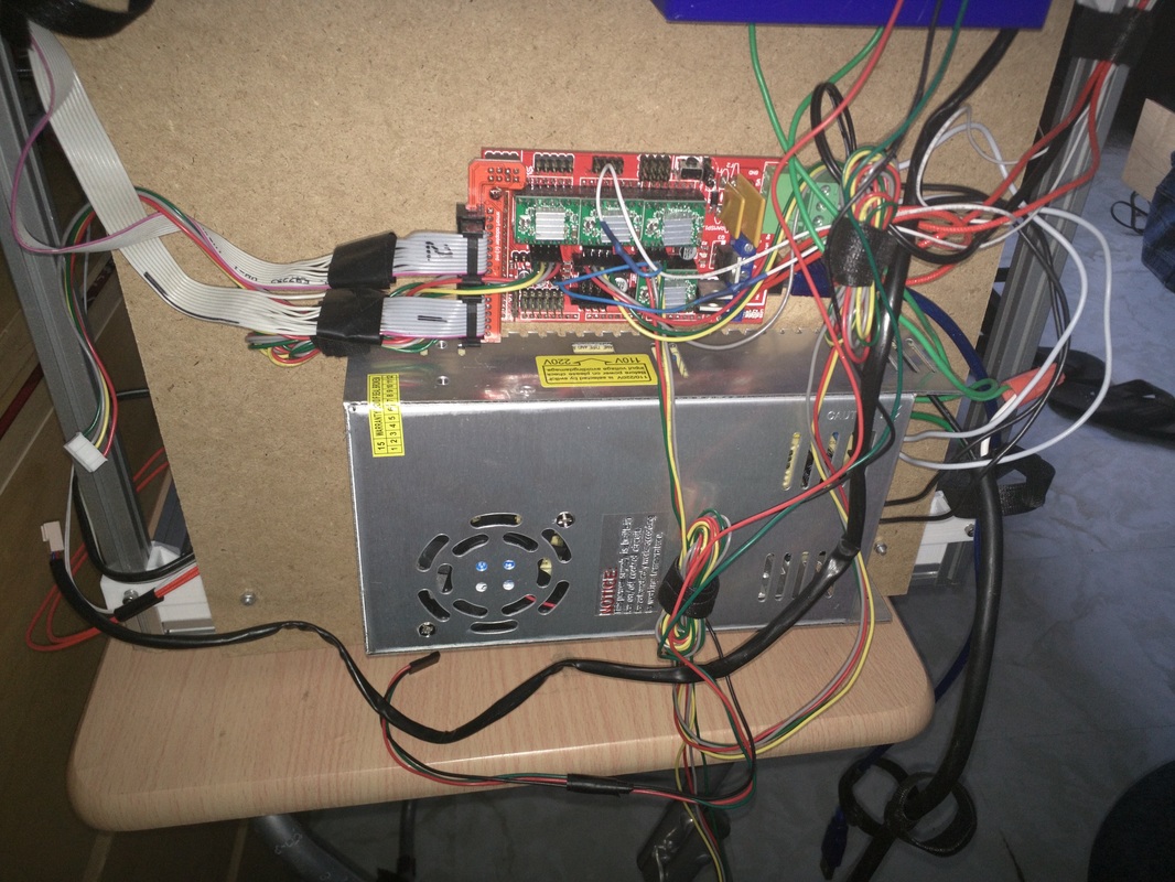
Hey guys, not much done in this update other than some designed parts. I designed 2 parts, one to hold the Arduino mega to one of the 1515 extrusions and two to hold the power supply to the lower part of the frame. Sadly the Mega holder had some miscalculations when it comes to the alignment of the screw holes, so I had to re-drill the holes in order for them to fit properly. After that it went pretty smoothly. I had also a problem with the brackets for the power supply. They were supposed to be fastened to the back of the power supply with M3 screws and everything was all measured and aligned properly but the problem was that for one of the screw holes that lies under the power supply for it to attach to the 1515 extrusion, the countersink got messed up because of the way the part was printed, so the screw did not sink, and it lifted the power supply enough for the back screws to not be aligned. So I ended up just attaching the power supply with some velcro ties and they hold it pretty nicely. I also did a lot of cable management for all the cables to go to the back. I used some velcro ties in order to get everything to move towards the back. I attached some of the components to the X carriage, to test the fit of all the part and they seem to work decently. the only thing that i am concerned about is that some of the part are taking way too much space on the XY carriage. I need to move some of the parts around in order to get to have as much travel space as possible. I will eventually get to do re-designs on the XY to get as much travel as possible. |
Angel MercedesElectrical Engineering student and lover of all things Open Source, 3D Printing, Electronics and Linux. Categories
All
Archives
May 2017
|

 RSS Feed
