|
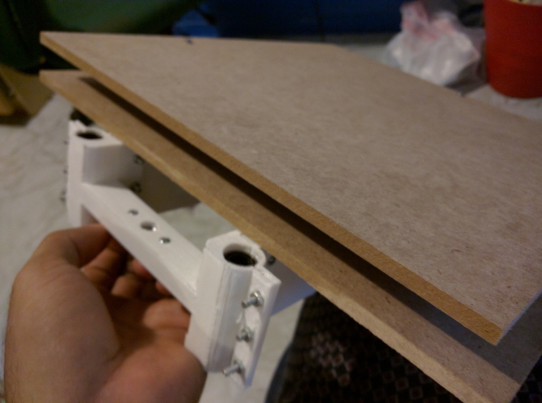
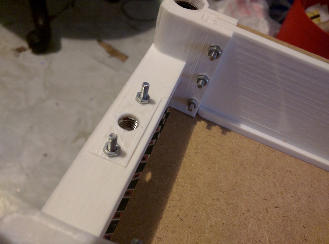
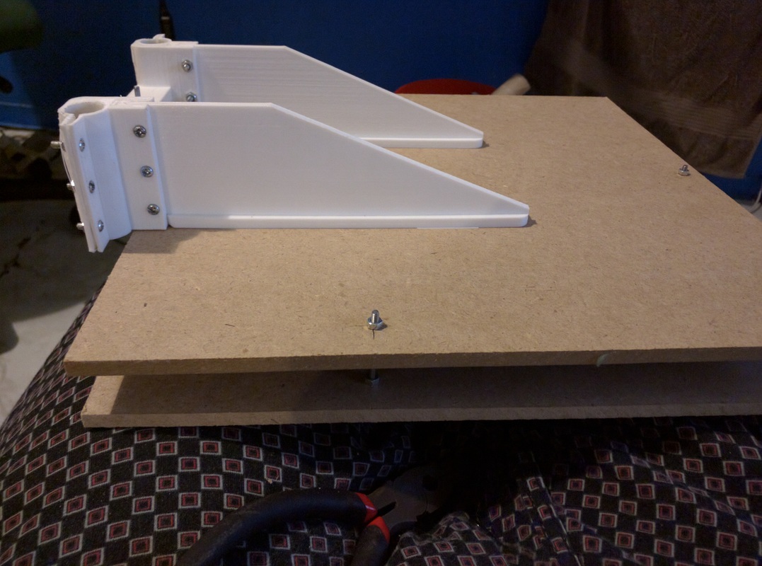
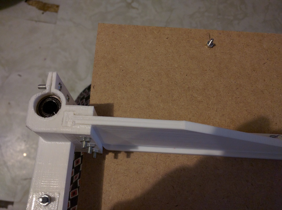
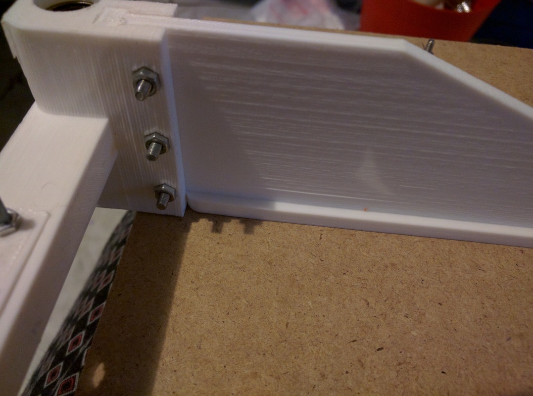
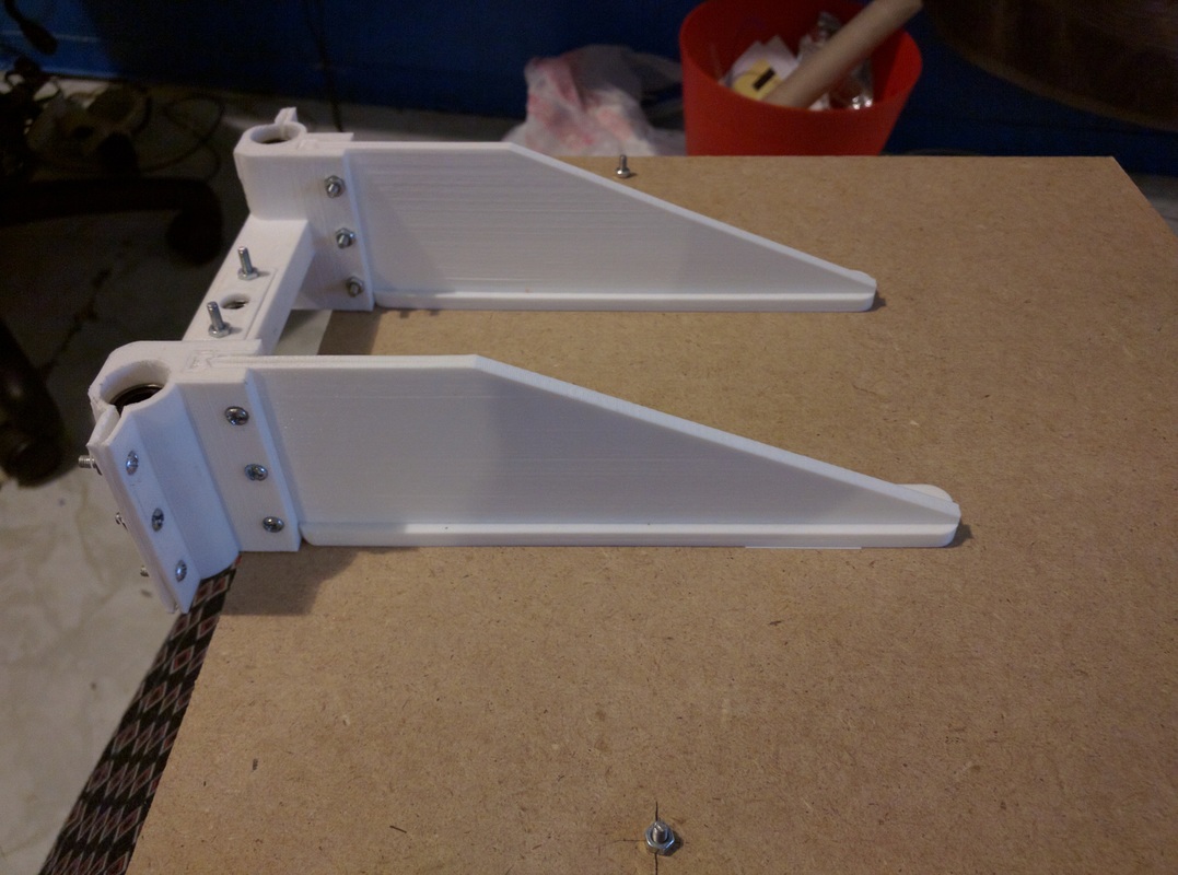
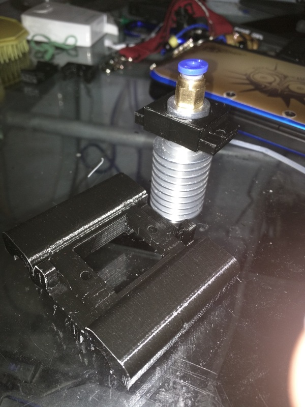
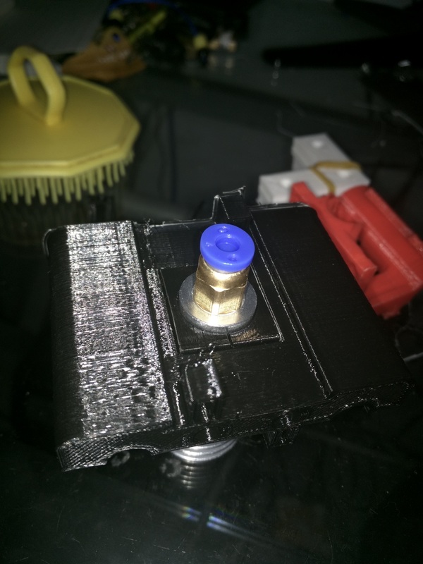
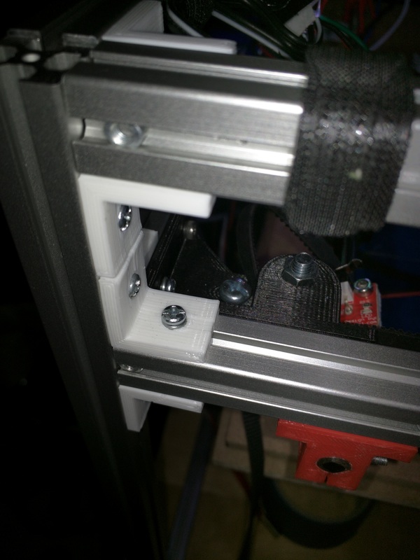
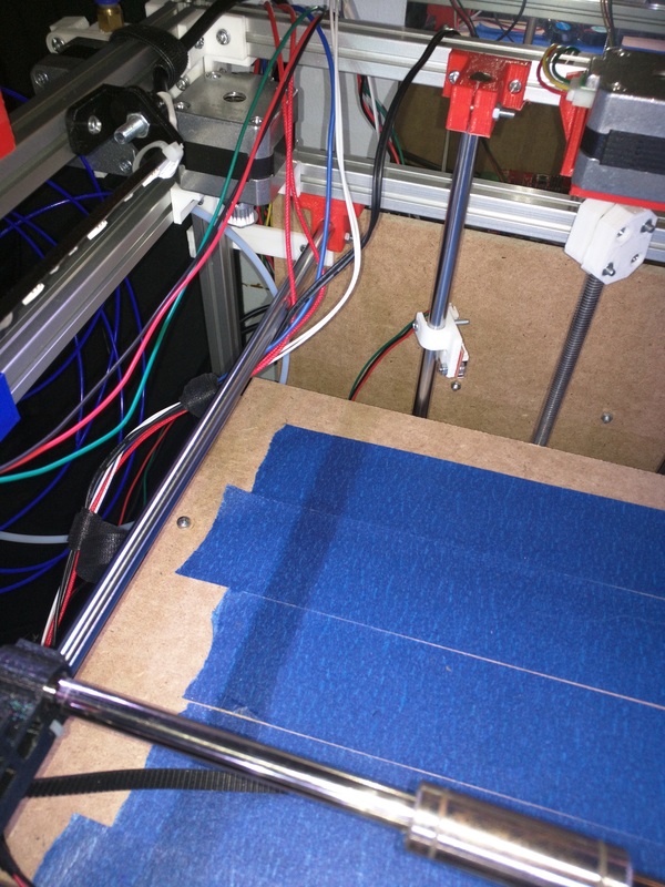
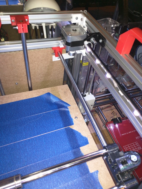
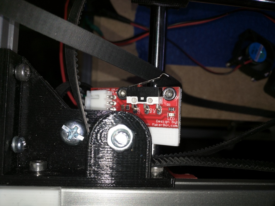
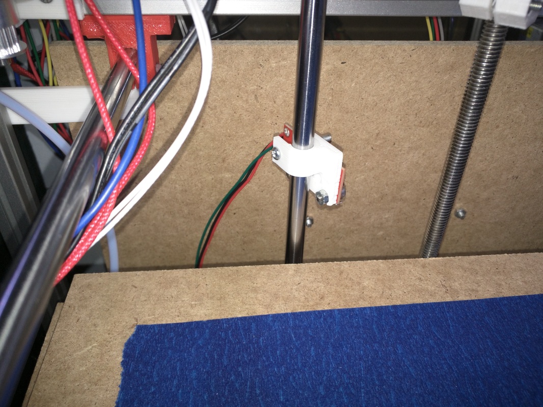
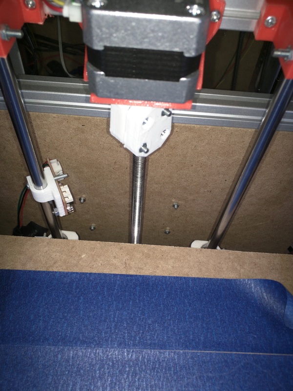
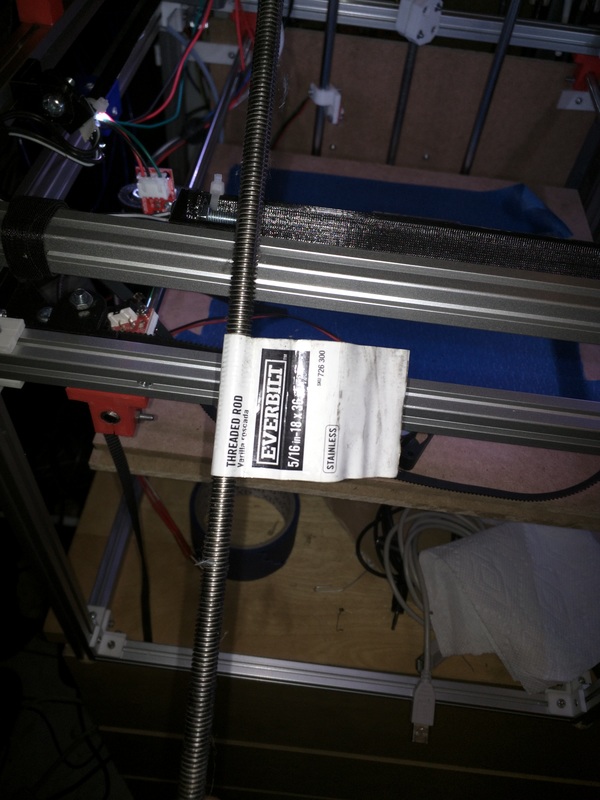
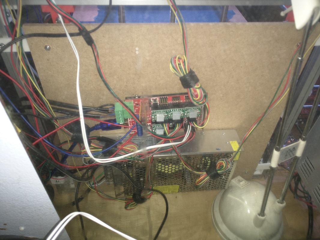
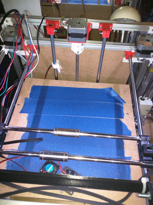
Hello everyone, today I bring you an update on what is the Heimdall 3D printer. This one is the third update of this series. A lot of changes have happened since the last time I wrote an update. A lot of these changes and fixes helped the printer actually become active and work properly. I will be explaining the changes made and why they were made, as well as how they improve printing. I have already uploaded some tests that I have done on YouTube, if you would like to see them, here they are: Why Version 2?I decided to make it version 2 because of the large amount of changes and improvements that have gone into this printer. There have been a lot of remade parts, improvements and tons of hours of printing and prototyping. Changes in Version 2Printing BedTons of changes went into the Z axis carriage. This is now divided into four parts that go in together. Two of these are the legs, which screw to the main body using three M3 screws. Then they use three M5 screws to attach to the wooden platform that holds the printing bed. The main body contains the two LM8LUU linear bearings, which are tightened by three more M3 screws. I wanted to use screws because I do not want to be breaking zipties to get to them. In the middle of the main body there is the nut enclosed inside of a compartment which holds it tightly in place. In order to get to it, two screws need to be removed and a cover. The nut stays inside very well and does not rattle at all, which is good for smooth movement. The nut is 5/16 - 18 Stainless Steel. The printing bed is made out of wood. This wood is very smooth, strong, lightweight and cheap. I used manual bed leveling for this one, because automatic bed leveling is a complete mess. The manual leveling uses 3 point bed leveling which is way easier to level the bed with than 4 point bed leveling. I used three very long M3 screws with it, these screws are also sprinted. They use springs from 3 similar pens that I had around which at the same time add some good tension. X-CarriageThis X-Carriage has been one of the most annoying things that I changed and redesigned. The stock one from the Fusebox was made so you could not use cooling fans blowing directly into the fins of the hotend, which leaded to overheats of it, creating jams and other issues. In this new design, the top part of the hotend sits on a block which is cut in half, which holds the hotend extremely tight and firmly. The good thing about this is that the hotend holder can be unscrewed from the carriage and taken out easily at any point. Not only that, but it can also be easily redesigned to fit any other sizes of hotends, of course, they have to be bowden. This carriage leaves enough clearance for the hotend to have a fan attached to it to be easily cooled. Frame SupportsI added new corner frame supports which are smaller and at the same time as strong as the older ones. These make the frame looks slicker to me and also take less space in comparison to the other ones. I have made other frame support for different parts to support it better but I have not put it in place yet. LightingI added three rows of RBG of 12V leds, each row has 6 leds. There is one row at the left of the frame, one at the front center and one at the right. They are powered directly from the 12V supply, in the future I will wire a switch and potentiometer. The switch will be to be able to turn them on and off whenever it is needed. Sometimes I print late at night and I would not like those leds shinning that late. The potentiometer will be for dimming them. These leds are mounted to a bracket which can be tilted up and down very easily. This allows for switching where the light will shine, improving visibility of the printing space. Z-Axis LevelingAs I said before, the auto bed leveling is gone in this version. This one will only use a simple endstop switch for the Z minimum. All the leveling is manual, which is easier to deal with when done right. I was going to use a proximity sensor that requires a metal bed, but I did not wanted to use a metal bed because of the weight. Endstops HoldersI am currently using different endstop holders for the Z min and Y min. The older ones used to randomly break just by having them on there, so I decided to switch them for stronger ones. They were taken from thingiverse, here it's the link to get them: http://www.thingiverse.com/thing:1108688 LeadscrewThe lead screw gave many issues for the older version of the Z axis of this printer. The older one was a 3/16 inches Zinc lead screw, which tended to bend extremely easily and those bends will create wobbles of the Z carriage. This new 5/16 lead screw is made out of Stainless Steel, which is way stronger and harder to bend. So far I have been getting very smooth movement and low amount of noise from this lead screw. I also made a coupler which attaches the 5/16 lead screw to the 5mm shaft of the stepper motor. If you need it, you can get it from here: http://www.thingiverse.com/thing:1270631 Electronics MountingI decided to use some of the leftover of the printing bed wood to make a place in which I could mount all the electronics where they are not on the way and also not visible from from the front. I might end up painting it in order to make it look better. XY-Axis PositioningThe XY-axis were moved to the 1515 extrusions located below the top ones. These give more stability and allow the top to be free for using the lighting. It takes away some Z travel distance but it is not too much. Anyways, Those are so far the updates and changes to the printer so far. There will be many more improvements coming this way so stay tuned.
0 Comments
|
Angel MercedesElectrical Engineering student and lover of all things Open Source, 3D Printing, Electronics and Linux. Categories
All
Archives
May 2017
|
 RSS Feed
